Hello,
I have just blown a fuse in my 2011 Bluemotion and found to my astonishment that there isn't a layout diagram for the fuse box in either the car or the manual. Manual said I need to go to the dealers to get it sorted and IMHO thats just ridiculous.
Does anyone have a diagram showing what the fuses are for so I don't get caught out one dark and lonely night .
Thanks in advance
Bluemotion fuse layout
Re: Bluemotion fuse layout
You might find this useful 
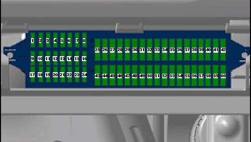
1 - 5A - Control unit in dash panel insert
ABS control unit
Mobile telephone operating electronics control unit
2 - 10A - Steering column combination switch
Onboard supply control unit
Rear window wiper motor
Windscreen and rear window washer pump
3 - 5A - Fuel pump relay
Engine control unit
Fuel supply relay
Fuel pump control unit
Control unit for structure-borne sound
4 - 2A - Steering column combination switch
5 - - Reserve
6 - 5A - Control unit in dash panel insert
7 - 5A - Headlight range control regulator
Number plate left light
Number plate right light
Onboard supply control unit
8 - 10A - Injector, cylinder 1
Injector, cylinder 2
Injector, cylinder 3
Injector, cylinder 4
Lambda probe heater
Lambda probe 1 heater after catalytic converter
Activated charcoal filter system solenoid valve 1
9 - 5A - TCS and ESP button
or 7.5A Tyre pressure monitor display button
Steering angle sender
ABS control unit
Stop/start system button
Data bus diagnostic interface
10 - 5A - Cruise control system switch
Steering column combination switch
Brake light switch
Clutch pedal switch
Onboard supply control unit
11 - 10A - Headlight range control regulator
or 5A Left headlight range control motor
Right headlight range control motor
Cruise control system switch
Onboard supply control unit
Cornering light and headlight range control unit
12 - 5A - Mirror adjustment switch
13 - 5A - Mechatronic unit for dual clutch gearbox
Selector lever
14 - 5A - Airbag control unit
Front passenger side airbag deactivated warning lamp
15 - 5A - Left washer jet heater element
Right washer jet heater element
16 - 5A - Parking aid control unit
17 - - Reserve
18 - 5A - Rear fog light cut-out contact switch
Control unit in dash panel insert
Rear left fog light bulb -L46-Onboard supply control unit
19 - 5A - Onboard supply control unit
20 - 5A - Steering angle sender
Control unit in dash panel insert
Fuel supply relay
Terminal 30 voltage supply relay
Low heat output relay
High heat output relay
21 - 10A - Onboard supply control unit
22 - 5A - Diagnostic connection
Climatronic control unit
Air conditioning system control unit
Mobile telephone operating electronics control unit
Ignition key withdrawal lock solenoid
23 - 5A - Selector lever
Rain sensor
Onboard supply control unit
Engine control unit
Data bus diagnostic interface
24 - 5A - Onboard supply control unit
Driver side heated exterior mirror
Front passenger side heated exterior mirror
25 - 5A - High pressure sender
Heater control unit
Radiator fan control unit
Air conditioning system control unit
Trailer detector control unit
Diagnostic connection
Humidity sender
Radiator fan control unit
Voltage stabiliser
Voltage stabiliser 2
26 - 7.5A- Air mass meter
Oil level and oil temperature sender
Power steering control unit
Heater element for crankcase breather
Starter relay 1
Starter relay 2
27 - 7.5A- Reversing light switch
28 - 10A - Lambda probe
Lambda probe after catalytic converter
Lambda probe heater
Lambda probe 1 heater after catalytic converter
29 - 10A - Fuel pressure regulating valve
Fuel metering valve
30 - 10A - Charge pressure control solenoid valve
Activated charcoal filter system solenoid valve 1
Exhaust gas recirculation cooler change-over valve
Coolant circulation pump 2 -V178-Heater element relay
31 - 10A - Sender for gas gauge
or 5A Automatic glow period control unit
Fuel supply relay
Additional coolant pump relay
Injector, cylinder 1
Injector, cylinder 2
Injector, cylinder 3
Injector, cylinder 4
32 - 10A - Fuel gauge sender
or 15A Fuel system pressurisation pump
or 20A Engine control unit
or 30A
33 - 5A - Clutch position sender
Brake light switch
34 - 15A - Control unit in dash panel insert
Left main beam bulb
Right main beam bulb
Onboard supply control unit
Left gas discharge light control unit
Right gas discharge light control unit
35 - 15A - Engine control unit
or 20A Fuel supply relay
36 - 7.5A- Right main beam bulb
37 - 25A - Heated driver seat regulator
Heated front passenger seat regulator
Heated front seats control unit
38 - 30A - Mechatronic unit for dual clutch gearbox
39 - 10A - Right dipped beam bulb
or 15A
40 - 30A - Fresh air blower switch
Fresh air blower control unit
41 - 10A - Rear window wiper motor
42 - 15A - Cigarette lighter
12 V socket
43 - 15A - Onboard supply control unit
44 - 5A - Anti-theft alarm ultrasonic sensor
Alarm horn
45 - 15A - Control unit with display for radio and navigation system
Multimedia control unit
Radio
Voltage stabiliser
46 - 20A - Headlight washer system relay
Onboard supply control unit
47 - 20A - Onboard supply control unit
Windscreen wiper motor
48 - 25A - Onboard supply control unit
49 - 30A - Sliding sunroof adjustment control unit
49 - 15A - Fuel pump relay
Fuel supply relay
50 - 25A - Driver door control unit
51 - 25A - Front passenger door control unit
52 - 30A - Rear left door control unit
Rear right door control unit
53 - 30A - Onboard supply control unit
54 - 15A - Left fog light bulb
Right fog light bulb
55 - 15A - Ignition coil 1 with output stage
or 20A Ignition coil 2 with output stage
Ignition coil 3 with output stage
Ignition coil 4 with output stage
56 - 15A - Left day driving light bulb
Right day driving light bulb
57 - 15A - Onboard supply control unit
58 - 20A - Brake servo vacuum pump
59 - 10A - Left dipped beam bulb
or 15A
60 - 15A - Control unit with display for radio and navigation system
Re: Bluemotion fuse layout
A fellow Bluemotion owner. Doesn't seem to be many of us.
Re: Bluemotion fuse layout
Thats brilliant, thank you very much. 
-
jamesagordon

- Bronze Member
- Posts: 235
- Joined: Wed May 02, 2012 10:37 pm
Re: Bluemotion fuse layout
how does the fuse layout apply to UK cars? The diagram layout is the opposite way round to my mine (mini fuses on right not left) how does it all flip and convert over?